Important notes: To add aquahub’s Buzzer, you must use a 12V Wall Transformer in your system. A 9V battery cannot handle these and battery life will be unacceptable. See How to build your own aquarium auto top-off system for instructions on converting from 9V battery to transformer power. Also, you must have a DPDT Relay. Relays purchased at aquahub prior to March 1, 2006 are SPDT and do not allow for addition of LEDs or buzzers as described below.
PLEASE NOTE: The following text describes a do-it-yourself project involving household 120 volt electricity, which, if mishandled, can cause shock or death by electrocution. Do not attempt this project if you are not comfortable working with electricity. Proceed with this project at your own risk.
LED
Follow these steps carefully to add an LED to your auto top-off system. The LED will light up when your system turns the reservoir pump on, alerting you to system operation. Note: the directions below describe the process for installing an LED with a built-in resistor. A regular LED without a resistor cannot withstand the voltage from the transformer. We no longer stock LEDs.
1. UNPLUG YOUR SYSTEM FROM THE WALL!
2. Read How to build your own aquarium auto top-off system in its entirety before attempting this add-on.
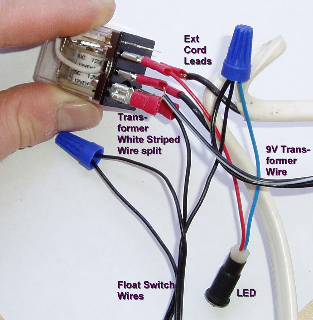
3. Your float switch circuit (the two float switches wired in tandem) connect to one transformer wire. Make sure that these connect to the solid (not white striped) transformer wire and add the blue wire from the LED into this connection by twisting it into the connection (strip the end first). Add or replace the wire cap. See the photo below.
4. Securely crimp a quick connect clip to the red lead of the LED and connect to post 3 of your relay.
5. Strip at least 1″ off the end of the white striped wire from the 12V transformer. Carefully divide the copper strands and twist each to divide the power that will come from the transformer into two separate bare wires. Attach quick connect clips to each of these. Be sure to bend the strands over themselves a couple times to create a thickness that can be securely crimped into the quick connect clips. Connect one clip to post 5 of the relay and the other to post 7, as shown in the photo below.
Posts 4 and 6 of the relay turn on the reservoir pump by completing the 120V circuit from your extension cord when the float switches complete the 9V power circuit to the relay coil (thus turning the relay on). Similarly, we are now using the other side of the relay – posts 3 and 5 to complete a 12V circuit through the LED when the relay coil is powered. We are simply using the 12V power from the transformer to power both the relay coil and the LED (that’s why we divided the strand from the white striped wire in two).
6. Re-insulate the relay connections with heat shrink or a project box before plugging the transformer or extension cord back into the wall.
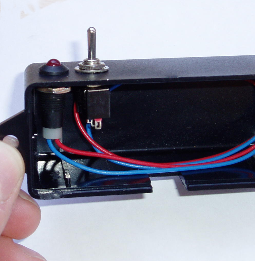
The photo below shows one mounting possibility for the LED in our Project Box.
Buzzer
Follow the instructions above for the LED. The black wire from the buzzer is equivalent to the blue wire from the LED. Add the buzzer’s black wire to the float switch circuit (step 3) and attach the red wire to the relay (step 4) exactly as described in the LED instructions. You can use both accessories by simply combining the blue wire from the LED and the black wire from the buzzer and then combining the two red wires from each device.
Re-insulate the relay connections with heat shrink or a project box before plugging the transformer or extension cord back into the wall.
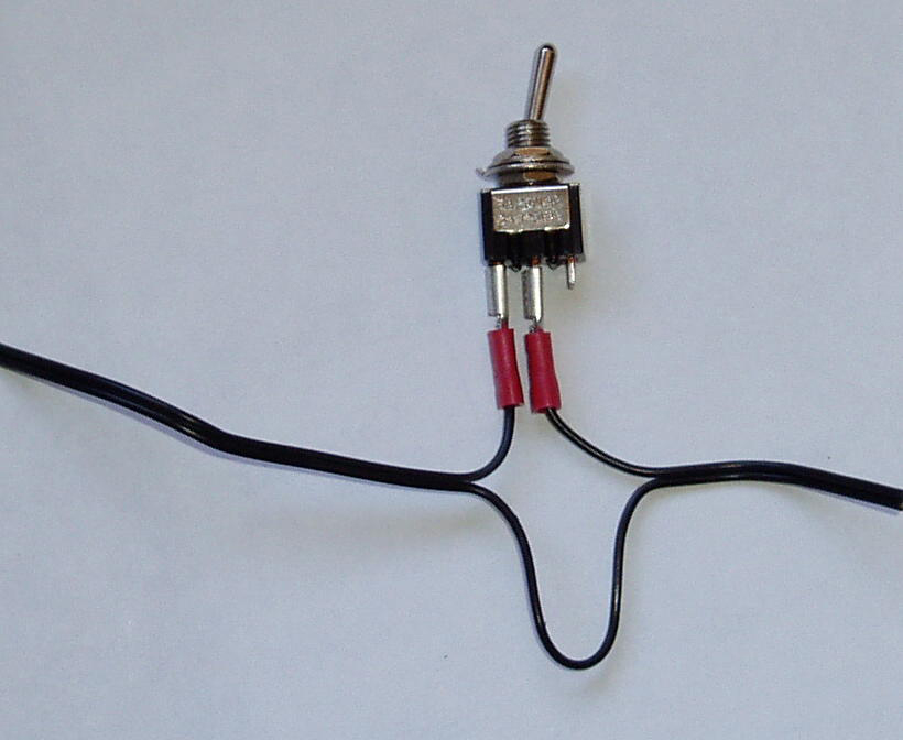
Toggle Switch (for turning your system on or off)
There are two wires coming from either of your 9V battery clip or your 12V transformer. Simply splice the toggle switch into one of these wires before it reaches the connections to your system. Use quick connect clips to attach one lead to the center prong of the switch and the other to either side prong of the switch, as shown below. The photo above shows a mounting possibility for the toggle switch.